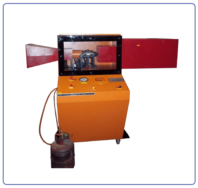
Computerized Aeronautical Gas Turbine Test Rig
(Product Code: AGTC01)
Product Description
The engine is a small compact free turbine engine. It comprises a gas generator and an accessory drive assembly. The gas generator incorporates a centrifugal compressor, an axial flow turbine rotating unit and an ignition and combustion system. The engine is mounted a sturdy Mild steel frame with caster wheels.
The engine is mounted on a load cell to measure the thrust of the engine. The engine is also provided with pressure, temperatures, air flow and fuel flow measurement system. The data from these sensors is passed to the PC on the USB interface and is displayed using the software provided. The data display and acquisition system require a PC running Windows 8. The software calculates the thrust, temperature and pressure readings using the Brayton cycle formulae. This calculated thrust can be compared with the measured thrust. The software also calculates the turbine entry pressure.
The user has access to a wide range of data acquisition, graph plotting and display functions. As well as the standard graph plotting functions, a special routine has been written to display H – S diagrams (Entropy – Enthalpy diagrams) which are of particular interest in thermodynamics.
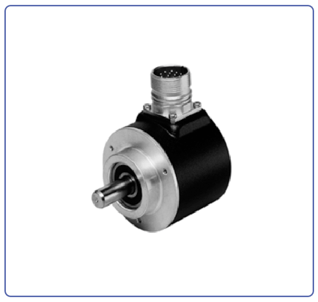
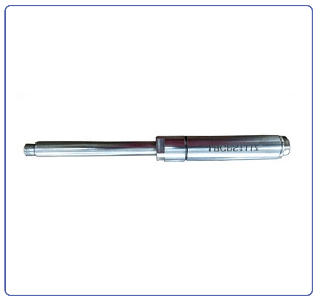
Engine Crank Angle Encoder
(Product Code: R&DU03)
Features
- Extensive range of Experiments
- Comprehensive teaching manual
- One year warranty
- Esthetically designed and finished Rig.
- High Quality instrumentation
Engine Crank Angle Encoder
(Product Code: R&DU03)
Features
The Engine Combustion Analyzer kit is a reliable tool to examine the combustion process of an internal combustion engine. This rugged, compact instrument provides the user with an efficient and effective method to evaluate and determine power cylinder combustion characteristics, and peak pressure balance. The engine combustion analyzer kit includes Software, combustion pressure sensor, and Crank Angle Encoder.
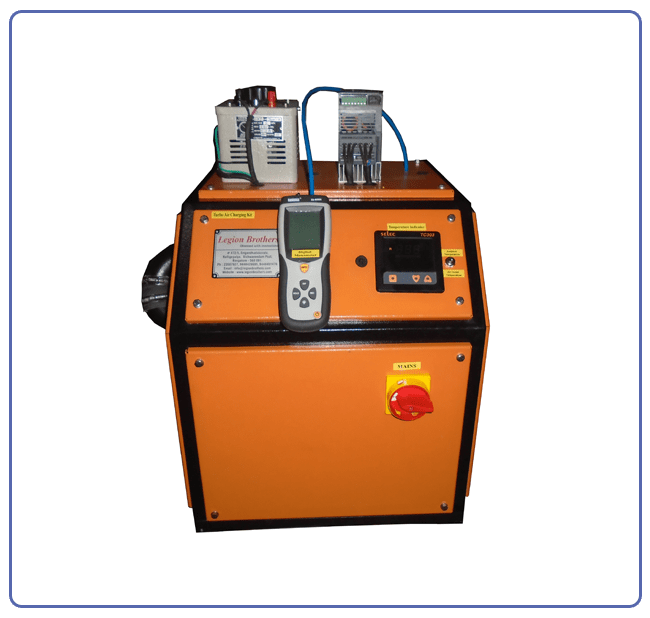
Exhaust Gas Recirculation System
(Product Code: R&DU06)
Product Description
In the present system the Exhaust gas coming out of the engine is passed to an EC (Exhaust cooler). The exhaust gases from the EC after cooling are passed via a valve and digital manometer. The digital manometer is provided in order to find the total amount of exhaust gas flow (when the EGR Control Valve is closed) and valve for controlling the flow. The digital manometer operates within the temperature range of 10- 50ºC; this is the reason for cooling the exhaust gas after the EGR system. In the main Exhaust line a tapping is provided for EGR system. The Exhaust gas from the tapping via a (stepper motor controlled) valve and is passed to the EGR Cooler, where the exhaust gas is cooled before sending it to the engine. A digital manometer is provided at the inlet manifold of the engine in order to know the flow of Exhaust gas to the engine. To allow desired percentage of EGR into the engine, the first step we should find the total flow of exhaust gas with the digital manometer provided after the EC. If the flow is supposing 40mm, therefore 40mm is the 100% at some particular load. If we wise to pass 10% EGR, now the EGR Control valve is slowly opened until we reach 4mm reading in the digital manometer provided at the intake manifold of the engine.
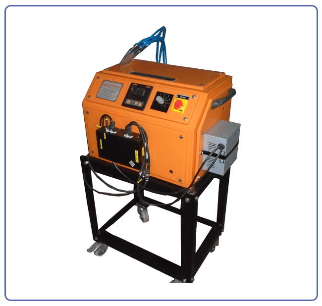
Turbo Air Charging System with Air Heating
(Product Code: R&DU10)
Product Description
The purpose of turbo charging is used for forced-induction of an internal combustion engine and to increase the density of air entering the engine to create more power. The system consists of a 3HP turbine blower connected with a variable Speed AC frequency drive. The outlet of the turbine blower is routed to the intake manifold of the engine via an Air Heating system, digital manometer, valve (V2), and finally to the engine intake manifold. A temperature sensor is also provided in the engine manifold to know the temperature of incoming air to the engine. Before using the turbo air charging system to the engine, the engines air consumption at different loads should be MAPPED. Whenever a turbo air charging system is not required Valve (V2) should be closed and valve (V1) should be in open condition.
Turbo Air Charging System with Air Heating
(Product Code: R&DU10)
Features
- Extensive range of Experiments
- Comprehensive teaching manual
- One year warranty
- Esthetically designed and finished Rig
- High Quality instrumentation
Data Acquisition System for IC Engine Performance Testing
(Product Code: R&DU12)
Product Description
Most modern engines today are controlled by an onboard computer, for purposes like Engine Operation, Optimization, Safety, Fuel efficiency, Pollution control etc… be it any purpose, the primary process of all such control systems is collecting and processing real world data. This is a device designed for measuring, processing and transferring engine test data to any computer, such data is primarily intended for educational and research use. It consists of Data Acquisition module; Sensors for IC engine performance testing, Sensor mounting accessories, Windows based computer software and Inter connecting cables, facilitating it to be readily installed on your existing petrol or diesel engines.